Tuesday, September 29, 2015

Activity 3 - Conducting Operations with Multi-Rotor UAS


Introduction: The focus of this activity was to work on our pre-flight process including device checks, filling out our pre-flight log and getting further familiar with the mission planning software. Fortunately, the weather cooperated and each team was able to successfully go through the entire process from start to finish.

Study Area: Conditions were ideal for flying and it did not rain until after we were done. Around a 5 mph wind and overcast clouds. For this exercise we went back out to the Eau Claire Sports complex and focused on the area featured below in (Figure 1).
(Figure 1) Eau Claire Sports Complex - shed is our primary focus

 This area is perfect for what we need, wide open with not a lot of obstacles and if timed right little to no people in the surrounding area. With flying these multi-rotors safety especially public safety is key. When operating these everyone has to be on the same page and be aware of what is going on in the area whether it be related to people, weather, disturbance in GPS signal, etc.

Methods: Before jumping right in to flying there are some crucial pre-flight steps needed to be done. This includes setting the GPS antenna (Figure 3) up high for best signal, going through the multi-rotor and assembling everything and beginning to do the pre-flight log. We used the same pre-flight checklist as the one found in my Activity 2 post (Figure 2). These checks are necessary for a number of reasons. The first being it is important to check all the hardware is in good working condition. The second being safety, if the area or conditions we are about to fly in are not good we cannot go through with the flight.
(Figure 2) Computer used for pre-flight log and Mission Planner

(Figure 3) Pole used to get our antenna higher, the higher it is the less ground interference. 

(Figure 4) Matrix Multi-Rotor
After doing the pre-flight checks we created a mission and sent it to the multi-rotor using Mission Planner (Figure 5). The missions all looked similar to the image below (Figure 4). For these flights we used the Matrix Quadcopter (Above Figure 4) with either the GEM sensor or the Canon SX260. With the sensors we still are focusing on having a high overlap (80%) to maintain the best quality processed image. Our flight times were around 4 minutes.
(Figure 5) Mission plan of area we imaged


Discussion/Results: Although we haven't gotten to image processing yet there are two gifs below (Figure 6 & 6) to give you a basic idea of what the multi-rotor does while following the mission we sent it. The more we get opportunities to do the entire process the better we get. The teams were much more familiar with the entire process after going through it once a week earlier. Once the images are processed I will add them to this post.
(Figure 6) RGB Images taken with SX260
(Figure 7) Near Infrared Images taken with SX20


Conclusion: The last two classes have been really important because they both have stressed the proper processes needed to do aerial imaging in the most effective, safe, and efficient way. With doing the pre-flight work and check lists it not only maintains the equipment better but helps catch problems that may occur during the flight and ultimately keeps everyone as safe as possible if done correctly. With the mission planner software it makes taking precise and well coordinated flights with imaging almost easy as long as you do the proper steps, make sure you are maintaining good GPS connection and if you are ready to take over if something goes wrong.  

Tuesday, September 22, 2015

Activity 2 - Using Mission Planner Software/Pre-flight Procedures

Introduction: 
This week we focused on the basics of using mission planner software that can be found for free here: Mission Planner. We also focused on pre-flight procedures and the importance of them before flying. The original plan was too go out and fly missions we came up with but the weather did not permit it so we did what we could with the weather situation.

Study Area/Methods:
To learn the basics about Mission Planner we played around with it in the lab before taking it outside and using it for imaging purposes. Being free and open ware the software has a lot of potential for further growth and customization. Ours was setup to be used with 3DRobotics aircraft and various popular cameras used for imaging. It was especially interesting experimenting using different platforms and cameras and seeing how by switching those affected how long it would take to capture an area. With the software you have a variety of options when it comes to coming up with a path or a full polygon. You can also adjust the speeds flown and the altitude of the device. There was also an area on the software that highlighted statistics for you aircraft including speed, altitude, how high of quality the gps lock was, etc.  Overall the software was very user friendly.

Below are some screen shots I took of some possible flights we could do.
 

On the left side you can see items such as how big of an area you are planning on capturing, the flight time needed and how many pictures will be taken. On the right you can select what platform will be flying and the sensor you are using for capturing images. You can also select the altitude and speed as shown on the right side of the screenshot.

After exploring the Mission Planner we decided to go outside and simulate a pre-flight check and get everything setup as if we were about to do a flight and capture images.
Dr. Hupy showing us how to go through the preflight checklist and connect everything to the computer.

3DR Iris 
While getting everything setup Dr. Hupy and Dr. P showed us the importance of having a strong GPS signal and using a pole to get the antenna above a lot of the interference. Dr. Hupy also walked us through a pre-flight check which we all ran through afterwards as the link below shows. To operate the platform it is best to have at least three people involved in the process, someone manning the computer and filling out the check list and once in flight monitoring using the computer. The next person is responsible for going through the aircraft making sure everything is in working condition and piloting while a third person has the role of spotting and assessing the ground situation while keeping an eye on the drone and working with everyone making sure everything is doing what it should be doing.

Pre-Flight Check List

These check lists are important to make sure safety is paramount. With pre-flight checks like this there is a good history of record keeping and it helps maintain the equipment and gives you credibility. It takes a little extra time in the beginning but once you get the hang of it the checks go quickly and will save you time and headaches in the long run. 

Discussion:
With the weather the way it was it made it hard to do any image capturing however what we did accomplish was very important and will help us with further classes and future flights. Everything we did makes sense and I can see the purpose for good record keeping. The Mission Planning software seems very effective and efficient and I'm eager to see it in action. 

Conclusion:
We accomplished everything we planned on doing except for image capturing but weather permitting we will have more opportunities to do so. Next time we go into the field we will be much more familiar with running the Mission Planner and also running through pre-flight checks to make sure everything is in working condition and we keep safety first and foremost.

Tuesday, September 15, 2015

Activity 1 - Image Gathering Fundamentals - Weather Balloon

Introduction

As this was the first week of class we started off with basic image gathering as most of us have very little actual field experience. As we build off of this week the methods will more than likely get more sophisticated and slightly more complex but using a tried and true method such as the one we used was a safe bet for our first time collecting data. The key topics we focused on were basic but crucial building blocks.

Study Area 

Our first area of study was one of which is close to home. For class we made the short journey over to the Eau Claire Sports Center. This location (Figure 1) includes an indoor complex, many soccer fields along with a playground and resting area. The conditions were ideal for the task with virtually no wind, temperatures in the low 70s with the occasional rain sprinkle made for optimal data collection weather.


Figure 1 - The highlighted area shows where we focused on data collection and gathering images. 
Method

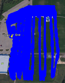
As we were mostly focused on the more general basic methods of collecting aerial images we used a very low tech method - a weather balloon. The original plan was to use a large kite but the unusual occurence of there being virtually no wind made that impossible. Nonetheless, we used a large weather balloon (Figure 2) filled with helium to accomplish our goal. The setup attached to the balloon is known as a picavet rig (Figure 3). A picavet rig is designed for nadir (straight down) images. Fortunately for us one was already setup but we were shown the steps that go in to creating one that works properly and allows for movement as the balloon's movement and orientation fluctuates. The rig was installed after the balloon was inflated and secured with line. The placement of the rig in relation to the balloon is important and it was attached approximately 15 feet below the balloon itself. The picavet rig held two cameras, one of which captured RGB images while the other took infrared images. Also on the rig was a GPS device that recorded the balloons movement in both .kml and .gpx format. The balloon was then released in to the air and we maintained it's height with the line at around 150 ft up. We selected this height because it would allow for clear and concise image overlap. Overlap is significant because without it there wouldn't be a way to accurately overlay images onto each other and create a single fluid image of the area we covered. We achieved overlap by walking in straight lines up and down the highlighted area in (Figure 1) with line spacing of around 30 ft. 
Figure 2 - Weather balloon with picavet rig attached

Figure 3 - Diagram showing the basics of a picavet rig

Results/Discussion

Later in the semester the class will be working on processing images but below are two pictures taken during this activity one from each camera. As I went through the images taken by the cameras I noticed that even without wind the picavet did move around quite a bit. Although the images aren't all perfect we seemed to accomplish a fair amount of overlap and it will be interesting to see how it turns out with the images stitched together.
 
RGB Color Image
Near Infrared Image
 
Taking a look at the .kml image (Figure 4) the GPS device recorded was very telling of the path we took while towing the balloon. You can tell by our path we started off doing very tight, close lines for major overlap but as the rain sprinkles picked up and people switched positions towing the balloon our lines got more separated from each other which may be a problem once we get to processing the images.  
Figure 4 - Image captured from Google Earth using our .kml data
While our weather balloon was in the air we also had a DJI Phantom taking some images of our rig and below is a very brief video showing the rig in action. 


Conclusion

This form of aerial image is not only effective but reasonably inexpensive pending you have access to decent cameras and a stash of helium. This method shows you that even with the most basic of materials and resources aerial imaging is not only possible but relatively easy to do without an excessive amount of technology and funds. As this being my first time doing any aerial imaging I was happy with the setup and starting to form a solid basis of knowledge and know how before really diving in to more advance methods to accomplish a similar result. It is crazy to me that not to many years ago the system we used for this activity was really all there was available and was regarded as highly effective and advanced for it's time. Most of today's methods built off of this method and those alike.